Route the arm as a mechanism, not as desk decoration
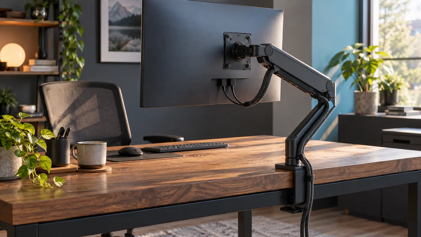
A monitor arm does two jobs at once. It carries a display through a defined load path, and it lets that display move. Cables add a third system that must follow the motion without becoming a tether. I therefore begin behind the screen, not at the visible desktop. I identify the VESA plate, tilt head, upper and lower pivots, vertical post, base, clamp or grommet fitting, and every cover or sleeve intended to hold a cable. The route has to respect each of those parts while keeping the support hardware open to inspection.
Shopping language can blur important distinctions. A clip holds a lead against an exposed arm. A removable sleeve surrounds a group while still opening for service. A snap-on raceway covers a shallow channel. An internal route may hide a cable inside a structural section, but it still needs a legitimate entry and exit. For a current overview of monitor arms that provide a cable-management sleeve or internal route, I would use those architecture words to narrow the field, then verify the actual diagrams, rated display range, supported desk surfaces, and connector openings for the exact arm under consideration.
The useful question is not whether the final photograph looks wireless. It is whether the monitor can visit every needed position while the connectors remain seated, the insulation avoids abrasion, and the arm carries only the load it was designed to carry. A cable bundle that makes the desk look clean while pulling on a video port or crossing a hinge has failed its main job. Hidden routing earns its place only when movement, inspection, and later removal remain understandable.
Draw a joint-by-joint motion trace
I sketch the arm in three ordinary states: the screen centered for focused work, pulled closer for detailed reading, and moved aside to clear the desk. A shared workstation may need a fourth state for another user. On each sketch I mark the joints that rotate, tilt, rise, or fold. The cable route is then drawn as a continuous line, with a small reservoir of slack only where relative movement demands it. This trace reveals whether one elegant sleeve is being asked to solve several unrelated motions.
A pivot changes cable length along the inside and outside of its arc. A tilting VESA head changes the distance between the display ports and the first fixed point on the arm. A post-mounted collar may rotate around a vertical axis while the lower arm folds toward the wall. Those movements should not be merged into one generous hanging loop. When slack is concentrated at one location, the nearest connector may still tighten while an unrelated section droops toward the desk.
Paper, removable tape, or a length of soft cord can represent the proposed path before a real lead is installed. The model stays outside the joint and does not enter the mechanism. Its purpose is to show which segment changes length between states. If the cord must cut across a pivot, scrape a fastener, or take a sharp turn to reach a sleeve opening, the route or arm architecture deserves revision before clips make the mistake permanent.
Confirm the support path before hiding it
Cable work should follow a sound mechanical installation, not conceal an uncertain one. I check that the display weight and mounting pattern fall within the arm maker’s stated limits, that any supplied plate and fasteners are correct for the monitor, and that the arm is assembled according to its instructions. The clamp or grommet fitting must bear on a permitted, sound desk surface. A decorative cable cover cannot compensate for a loose plate, damaged edge, unsuitable hollow panel, or unsupported overhang.
Extension changes leverage even when the displayed weight does not change. The arm usually places more demand on its base when the screen is pushed far from the post. That does not create a universal safe reach number; the rated instructions and real desk construction control the decision. It does mean the planned cable test should include the farthest position that the setup will actually use. An arm that sags, shifts at the base, or exposes desk damage should be corrected before the cable route is judged.
I keep adjustment fasteners, tension points, release tabs, and the clamp screw visible. A sleeve should not wrap around a structural connection or prevent a routine inspection. If a cover can be removed only by unloading the arm, that service sequence belongs in the record. The finished route is not a seal placed over the hardware. It is a removable layer that leaves the load path legible.
Measure the connector gate, not just cable diameter
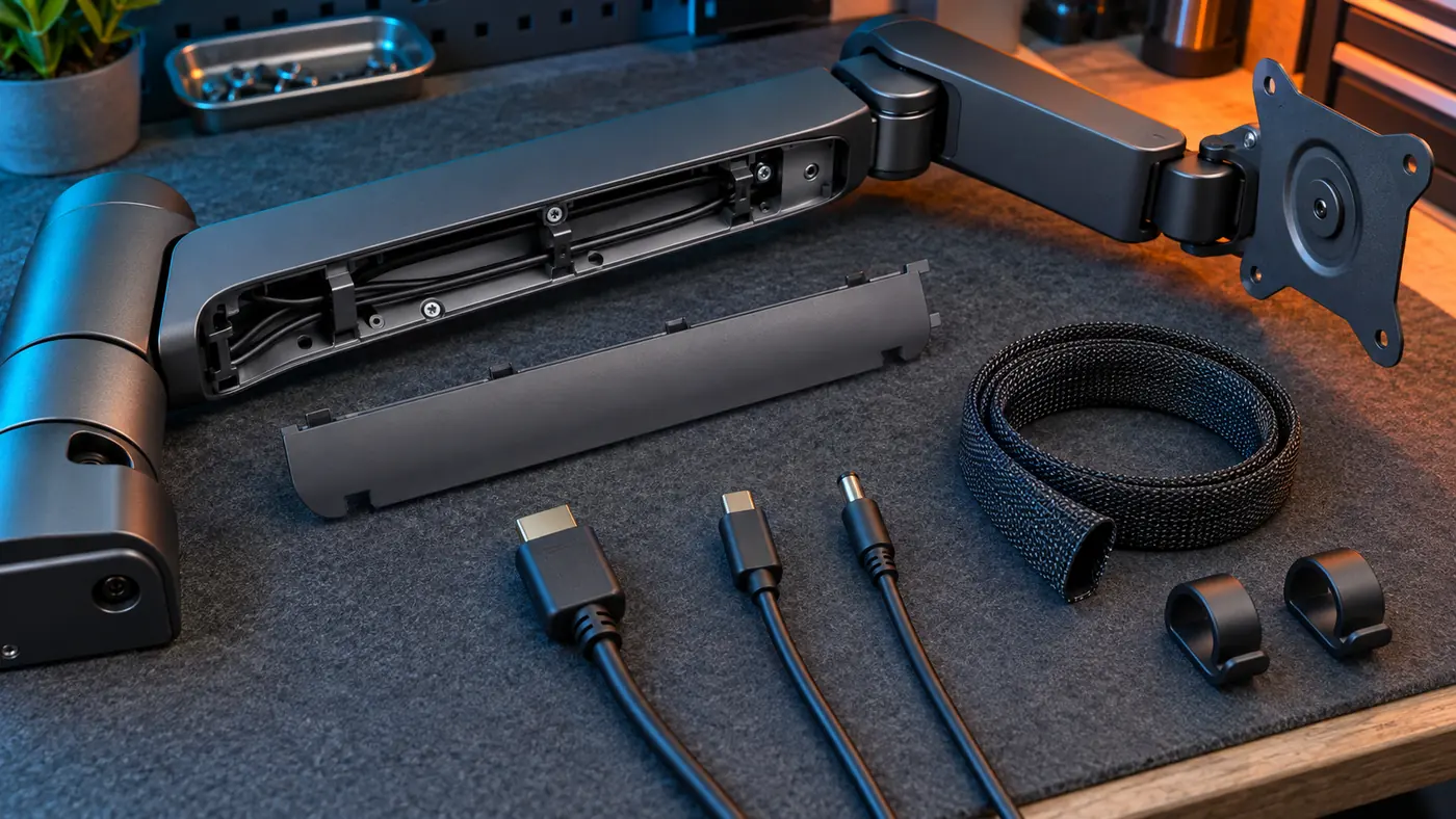
A thin cable can end in a connector much wider than the sleeve that appears to fit it. I inventory both ends of every lead, including right-angle housings, ferrite bulges, detachable adapters, and locking features. The relevant passage is the narrowest opening through which the largest non-removable head must travel. Forcing a plug through a decorative slot can damage the plug, deform the cover, or make later removal impossible without dismantling the display.
An internal channel also has a usable shape, not merely an advertised capacity. Rounded power leads, flat video leads, braided jackets, and stiff strain-relief boots occupy space differently. I lay the unplugged leads side by side without crushing them and compare that group with the channel entrance, bends, and cover latches. A cover that closes only under pressure is reporting an overfilled or poorly arranged route, not a need for stronger hands.
Installation order matters. A connector may pass through an entry while the arm is unloaded but become blocked after the VESA head or base is assembled. Another design may allow the channel cover to open along its length, avoiding the need to thread a head at all. I favor routes whose service logic matches the equipment: individual leads can be identified, removed, and replaced without disturbing the monitor support.
Put slack where movement occurs
Useful slack is local and assigned. Behind the display, a modest loop lets the screen tilt or rotate without pulling the ports. Between arm sections, the cable follows the maker’s intended clips or sleeve and stays outside the pivot axis. Below the base, another controlled length allows the arm to swing while the fixed descent toward a dock, power point, or desk tray remains stable. These reservoirs answer different movements and should be observed separately.
Too little slack announces itself as a connector that turns, a lead that becomes a straight line, or an arm that rebounds from the intended position. Too much slack can brush the wall, fall across a keyboard, catch a decorative object, or fold into a hinge. I move the display only while watching the rear path, and I stop at the first sign of tension, rubbing, migration, or unexpected resistance. The arm should never be used to pull a cable into place.
Cable length is therefore a routing dimension. A lead that reaches the device in the centered state may be too short for the extended state once the path follows every arm segment. A needlessly long lead creates storage work at the fixed side. I choose length after the route is drawn, preserving gentle bends and accessible connections rather than stretching one cord diagonally between endpoints.
ROUTE ARCHITECTURE
Compare access before concealment
| Format | Useful property | Acceptance question | Likely fit |
|---|---|---|---|
| Open arm clips | Immediate visibility and easy single-lead changes | Can a lead stay captured through the full motion without touching a joint? | Frequently changed single-display desk |
| Removable braided sleeve | Groups compatible traveling leads while remaining flexible | Do both connector heads pass, and can the sleeve stay out of every pivot? | Moderate bundle with accessible endpoints |
| Snap-on external raceway | Integrated appearance with a defined cable lane | Will the cover close freely around the real bundle and open for service? | Stable cable set with compatible heads |
| Internal arm channel | Minimal exposed run when the arm provides genuine entries | Is the threading sequence reversible after installation? | Long-lived configuration with documented service access |
Separate the traveling bundle from the fixed desk network
Only the cable length that truly moves with the monitor belongs on the arm. After the base, the route should transition to a fixed desk path: a rear rail, vertical leg descent, dock location, or another support approved for the equipment. A heavy power brick should not hang from the arm or from a display connector. Its weight belongs on a stable ventilated surface, with the flexible lead carrying only itself through the moving section.
Power, display, USB, and network leads may share a physical route only when their equipment instructions permit it and the bundle remains serviceable. I do not invent electrical separation distances or claim that a sleeve changes a cable’s rating. If interference, heat, damaged insulation, or uncertain power compatibility appears, the answer is to stop and follow qualified manufacturer or technical guidance, not to hide the issue inside a thicker wrap.
Docks deserve special treatment because one upstream lead can replace several traveling cables while creating a new fixed cluster. I place the dock where its ports, power supply, and ventilation remain reachable. The short monitor-facing leads travel with the arm; charger bricks, network connections, and surplus length stay off the moving structure. This division usually makes the sleeve easier to inspect and the workstation easier to change.
Run a slow, unpowered motion cycle
The first routing test happens with devices shut down and disconnected as their instructions require. I support the monitor normally, then guide it through the planned states with one hand while watching the cable path from the side. I do not force the arm to its mechanical stops or perform an improvised load test. The purpose is simply to verify that ordinary reach, tilt, rotation, and parking movements do not tighten or trap a lead.
At each state I inspect four points: the display ports, the first sleeve entry, every exposed joint transition, and the base exit. The cable should keep a gentle approach to the connector, remain outside pivot seams, stay seated under the intended cover without bulging, and reach the fixed desk route without becoming a hanging handle. A removable paper marker placed beside a lead can reveal migration; it is removed before power returns.
Only after the unpowered cycle passes do I reconnect the equipment in the stopped, supported position. Normal operation is confirmed without moving the arm. A second short cycle can then be performed according to the equipment guidance, followed by another visual inspection. Intermittent display loss, connector movement, unusual warmth, odor, visible damage, or a changed support position is a stop condition, not a prompt to repeat the movement more aggressively.
Compare routing architectures by service cost
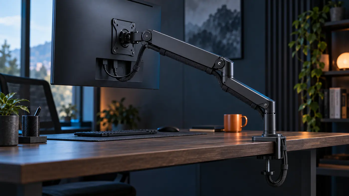
Routing styles trade concealment for access. Open clips expose the entire lead and make replacement simple, but they may leave more visual interruption. A flexible sleeve gathers several compatible leads and can bridge gentle arm sections, yet it needs a controlled entry and must not become a tight rope across a pivot. Snap-on raceways can look integrated while limiting connector size or bundle depth. Fully internal channels reduce visual clutter only when their covers, bends, and service sequence remain practical.
I compare the architecture against the likely change pattern. A fixed single display with long-lived cables may benefit from a more enclosed route. A development desk that swaps laptops, docks, and capture devices needs quick identification and removal. A shared screen that moves through a large arc needs visible evidence that local slack remains. The most hidden option is not automatically the most suitable option.
Finish quality matters after the functional gate. A cover should sit flush without forcing, clips should match the arm’s intended attachment points, and a sleeve should not fray, slide into a joint, or obscure a warning or adjustment. If the route requires tape over moving hardware, tight coils at the ports, or a cable tied to the clamp screw, I would reject that layout even if it photographs neatly.
Keep a route ledger for the next change
A route is easiest to maintain when its logic is recorded while it is still obvious. My ledger names each cable, its two endpoints, the arm segment it follows, the motion it serves, and the fixed path it joins below the base. A rear photograph shows the display loop, joint clearances, sleeve entrances, and base exit without including private screen content. The record turns a later equipment change into a comparison rather than a guess.
The ledger also lists the approved monitor position range used during the motion cycle and the conditions that would trigger a reroute: a different display, a new dock, a changed desk, a replacement lead with a larger connector, a sleeve that will not close freely, or evidence of abrasion. It does not claim that the installation has been certified. It simply preserves what was checked and why the route was accepted.
I review the path after moving the desk, cleaning behind the display, changing screen height, or sharing the station with a new user. The aim is not to keep every cable invisible. It is to preserve an articulated system in which the support remains sound, each connector stays relaxed, motion remains unforced, and the next person can understand how to open the route without damaging it.
MOTION-CYCLE RELEASE
Accept the route only when every gate remains visible
- 01
The display, VESA pattern, arm rating, fasteners, desk surface, and clamp or grommet installation agree with the applicable instructions.
- 02
Every connector head can enter and leave its sleeve or channel without force or destructive disassembly.
- 03
The display loop, arm-following section, and base exit each provide only the slack needed for their own motion.
- 04
No lead crosses a hinge axis, pivot seam, tension point, release tab, clamp screw, sharp edge, or ventilation opening.
- 05
Power bricks, docks, adapters, and surplus length rest on a stable fixed surface rather than hanging from the moving arm.
- 06
A slow unpowered cycle covers every ordinary screen position without tension, rubbing, snagging, bulging covers, or base movement.
- 07
The route can be opened for inspection, one lead can be identified, and the fixed desk descent remains clear of feet and chair travel.
- 08
A dated route ledger and rear reference image exist for later changes, without claiming professional certification.